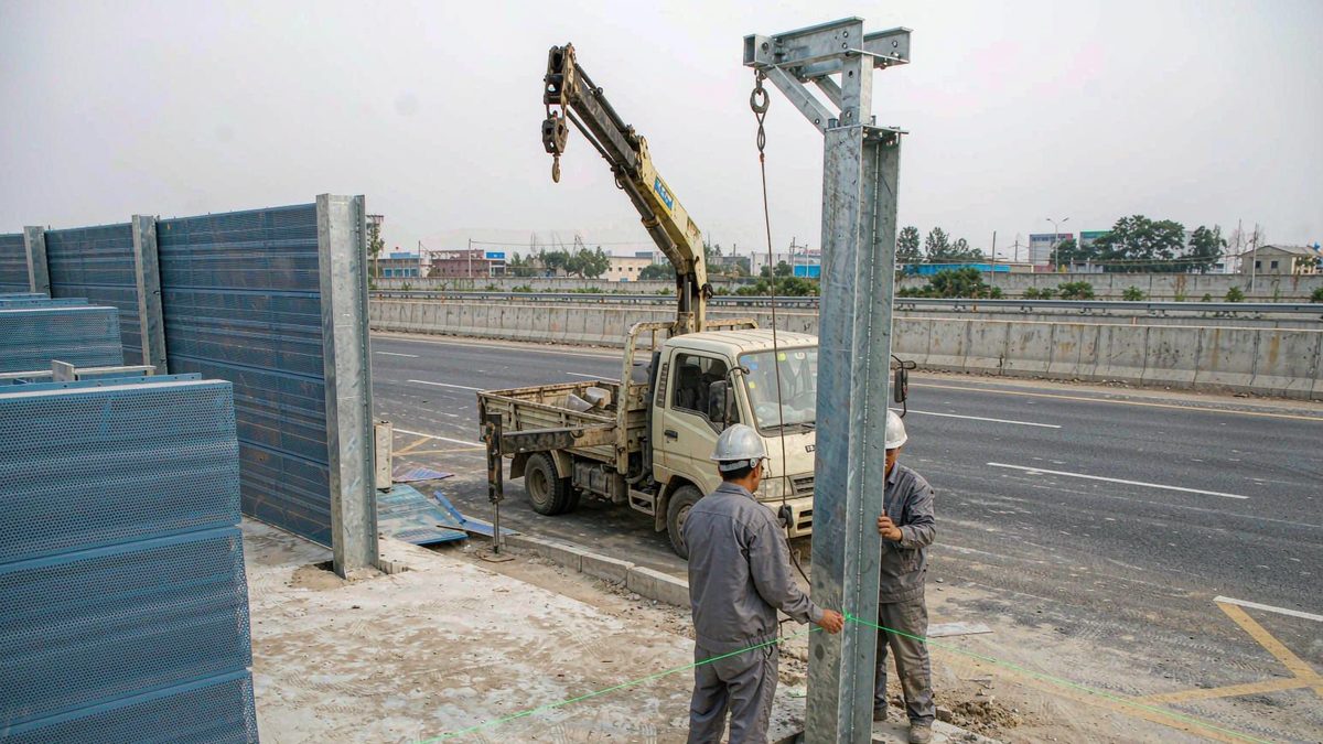
Insertion Loss Explained: How to Size a Noise Barrier
Insertion loss is geometry, not panel spec. A worked Maekawa example, the height-versus-cost curve, and the wind and reflection corrections that decide acceptance.
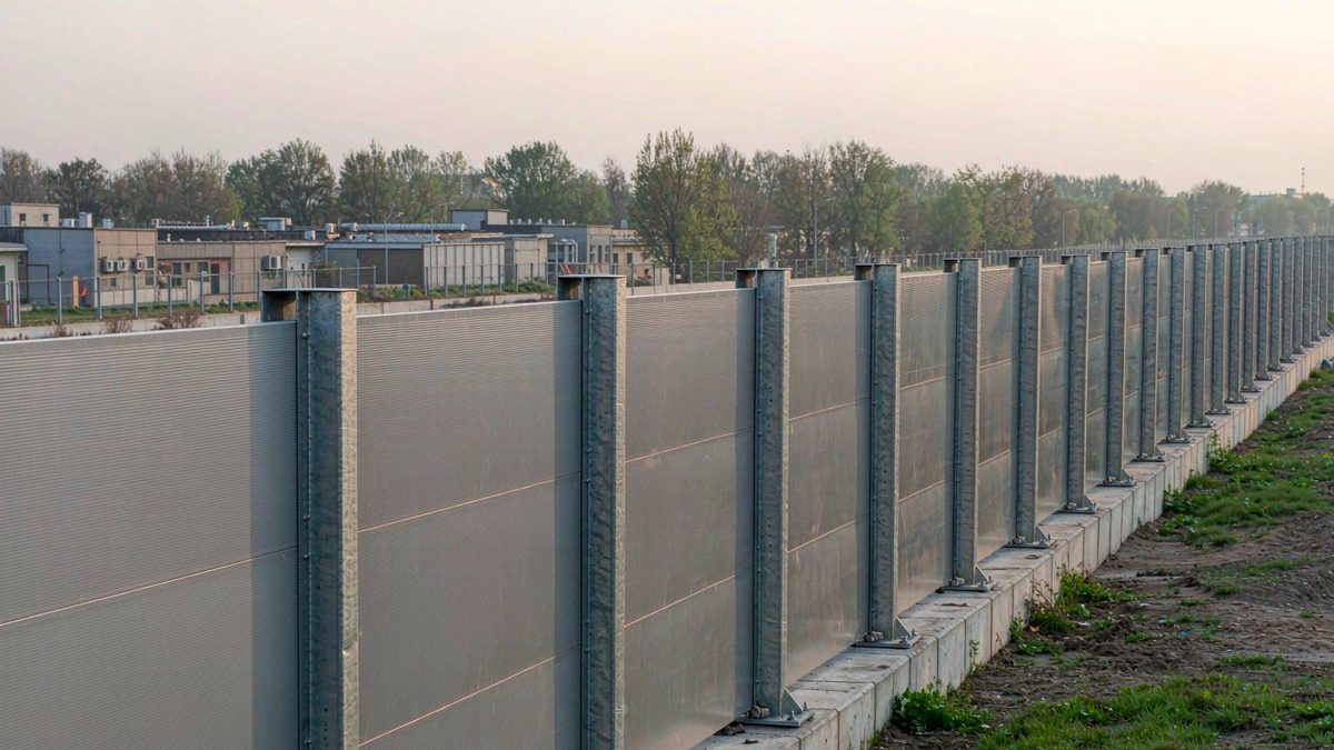
Four numbers that get used interchangeably, and should not be
| Term | What it measures | Typical value | Where it belongs |
|---|---|---|---|
| Insertion loss (IL) | The drop in sound level at a receiver after the barrier is built, including diffraction over the top | 8–15 dB(A) | The design target, site-specific |
| Transmission loss (TL, or Rw / STC) | How much sound passes through the panel | 30–35 dB | A panel property, tested in a lab |
| Absorption (NRC) | How much sound the traffic face absorbs instead of reflecting | 0.85 | A panel property, tested in a lab |
| Sound power of the road | What the source emits before anything is built | 80–90 dB(A) at 10 m | Input to the calculation |
A barrier with STC 32 can deliver 6 dB(A) of insertion loss if it is in the wrong place, and a barrier with STC 28 can deliver 14 dB(A) if it is in the right place. Transmission loss is a property of the panel. Insertion loss is a property of the site.
The error that costs the most money is buying on NRC. NRC tells you how much sound the panel absorbs on its face; it says nothing about how much gets past the top edge, which is where 80% of the remaining energy goes.
How insertion loss is actually calculated
The standard engineering approach is Maekawa's diffraction formula, still the basis of most national highway methods:
IL ≈ 10 log₁₀(3 + 20N), where N = 2δ / λ
- δ is the path difference: the length of the diffracted path over the top edge minus the straight-line distance from source to receiver.
- λ is the wavelength at the frequency of interest (343 / f).
That is the whole model. Everything else — ground, wind, reflections — is a correction on top.
A worked example
A four-lane highway. Barrier 3.0 m high, 6 m from the near lane edge. Receiver is a first-floor window 20 m behind the barrier, ear height 1.5 m. Source height for tyre noise is taken as 0.5 m.
- Direct path, source to receiver: 26.02 m
- Diffracted path, source over the top edge to receiver: 6.50 + 20.06 = 26.56 m
- Path difference δ = 0.54 m
- At 500 Hz, λ = 0.686 m, so N = 2 × 0.54 / 0.686 = 1.57
- IL = 10 log₁₀(3 + 31.4) = 15.4 dB
At 250 Hz the same geometry gives 12.7 dB; at 1,000 Hz, 18.2 dB. Road traffic is dominated by 250–1,000 Hz, so a realistic A-weighted figure for this wall is 12–14 dB(A) — the single number that belongs in the specification, not the 18 dB that the 1 kHz band suggests.
Why more height stops paying
Same geometry, wall height varies:
| Wall height | Theoretical IL at 500 Hz | Gain over previous | Panel area index | Cost index | Cost per extra dB |
|---|---|---|---|---|---|
| 2.0 m | 11.1 dB | — | 0.67 | 0.72 | — |
| 3.0 m | 15.4 dB | +4.3 | 1.00 | 1.00 | 0.065 |
| 4.0 m | 18.2 dB | +2.8 | 1.33 | 1.45 | 0.16 |
| 5.0 m | 20.3 dB | +2.1 | 1.67 | 2.00 | 0.26 |
| 6.0 m | 21.9 dB | +1.6 | 2.00 | 2.65 | 0.41 |
The last column is the one to take to the budget meeting. Going from 3 m to 4 m costs about 0.16 index points per decibel. Going from 5 m to 6 m costs 0.41 — two and a half times as much for the same decibel. In most projects the economic optimum sits between 3 and 4.5 m, and the way to reach a target above that is geometry, not height: bend the top, move the wall closer to the source, or enclose.
There is also a practical ceiling. Field measurements on highway barriers rarely exceed 18–20 dB(A) of insertion loss regardless of height, because once the direct path is suppressed, flanking paths take over: sound around the ends of the wall, through the base gap, through the panel joints, and through the ground.
The three corrections that decide whether the prediction holds
Ground
Soft ground — grass, soil, gravel — between barrier and receiver adds 1–2 dB at low frequencies compared with an acoustically hard surface. It is a real effect and it is why a barrier beside a park performs slightly better than the same barrier over a paved yard. It is not a design variable you can rely on.
Wind and temperature
This is the correction that ruins acceptance tests. Downwind, sound is refracted downwards and insertion loss can drop by 5–10 dB. At night, a temperature inversion does the same thing: the air near the ground is cooler than the air above, sound bends down, and the barrier that measured 13 dB at 14:00 measures 6 dB at 02:00.
For a residential receptor, the night case is the one that generates complaints, and it is the case most likely to be missing from a design report prepared under a daytime default. Specify the meteorological condition, and require the design to hold under a light downwind case (typically 2–3 m/s at 45–90° to the road).
Reflections
Two parallel barriers on opposite sides of a dual carriageway form a canyon. Each reflects energy back across the road, and measured insertion loss is commonly 3–6 dB(A) worse than the free-field prediction. An absorptive face recovers 2–4 dB of that. On an urban viaduct with buildings on both sides, the same mechanism applies even without a second barrier: the building façade is the reflector.
What the factory needs from you to check a design
A supplier cannot size a barrier from a photograph. Six inputs close the loop:
- Cross-section showing carriageway edges, barrier line, and the receptor, with distances.
- Receptor height and use — ground floor, first floor, sixth floor, hospital ward, classroom. Height above the barrier crest is what decides whether a roof is needed.
- Traffic data: AADT, percentage of heavy vehicles, design speed. Heavy vehicles at 90 km/h dominate the spectrum above 500 Hz; a 60% HDV mix can add 4–6 dB(A) at source.
- Road surface: porous asphalt is 3–5 dB(A) quieter at source than SMA, which changes the barrier requirement before a single panel is ordered.
- Target and its basis: dB(A) at the façade, and whether it is Leq or L10, day or night.
- Design wind load for the site, so the acoustic height and the structural height agree.
How to read the acoustic report you were sent
Three checks catch most of the problems:
Is the target at the façade or free-field? A level measured 1 m from a building façade is typically 3 dB higher than the free-field level at the same point, because of the reflection. A report that mixes the two can be out by 3 dB without anyone noticing.
Was the barrier modelled, or was an insertion loss assumed? Good reports show the diffracted path and the ground and reflection corrections. Reports that say "barrier 3 m, attenuation 15 dB" have assumed the answer.
Does the barrier actually intersect the sight line? If the top of the wall is below the line from the source to the receiver, the model should return near-zero. When it does not, the geometry is wrong.
Five things a barrier cannot fix
- A source above the wall. Truck exhaust stacks, the top of a rail car, a cooling tower on a roof. The barrier has to be higher than the source, not higher than the road.
- Structure-borne vibration. Ground-borne rail vibration passes under and through the wall and re-radiates inside the building. That needs a floating slab, not a panel.
- A gap. A 20 mm continuous gap at the base costs 2–3 dB(A). So does an unsealed panel joint, and both are invisible in a completed photograph.
- The near field. A barrier gives almost nothing to a receiver standing 3 m from the traffic, because there is no path difference to exploit.
- A wrong target. If the planning condition was written against a free-field level that the road never actually produced, no wall will satisfy the measurement protocol.
The short version
Size the wall on the path difference, not on the panel specification. Check the height against the cost curve before committing to it, because the fourth metre costs two and a half times what the first one did. Bend the top if the height is capped. Specify absorptive faces wherever the wall can see a reflector. Design for the night, downwind case, and seal the base — because that is the hour, the condition and the detail where a barrier quietly stops working.