How to Install a Noise Barrier: Foundations, Posts, Panels
Step-by-step noise barrier installation: foundation selection, post tolerances, panel insertion, and the base-seal detail that decides whether the wall hits its dB target.
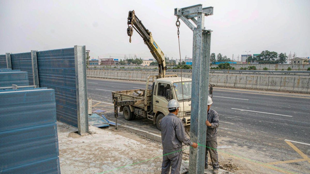
Before the first post goes in
Three surveys decide whether the installation runs at 120 m a day or stalls at 30.
Setting out. The barrier line is rarely the line on the drawing. Kerbs move, verges are wider than specified, and a 2 m post module almost never lands exactly on the end of the wall. Set out from a fixed structure at both ends, distribute the residual over the last two bays, and record it. If the drawing says 2.0 m and the site gives 2.08 m, do not squeeze 4 mm out of every bay — the panel end clearances will close up and the assembly will bind in summer.
Underground services. Drainage runs, ducts, and fibre are routinely 400–600 mm below the verge, exactly where a 1 m deep pad is going. A trial pit every 20 m is cheaper than cutting a duct.
Ground conditions. A 3 m wall on competent ground takes an 800 × 800 × 1000 mm pad. The same wall on fill, soft clay or made ground needs either a wider pad or a short bored pile, and that decision belongs to a geotechnical engineer, not to the erection crew on the morning of the pour.
Foundation options, and when each applies
| Condition | Foundation | Typical detail | Relative cost |
|---|---|---|---|
| Competent soil, verge ≥ 1 m | Isolated pad per post | 800 × 800 × 1000 mm, C25 | 1.0 |
| Continuous verge, poor soil | Strip footing | 600 wide × 800 deep, continuous | 1.4–1.8 |
| Narrow verge, soft ground | Bored pile | Ø300–400, 3–5 m deep | 2.0–3.0 |
| Rock at shallow depth | Rock anchor | M24, 600 mm embedment, grouted | 0.9–1.3 |
| Bridge deck or viaduct | Cast-in socket or chemical anchor | Socket 300 mm, non-shrink grout | 2.5–4.0 |
| Existing retaining wall crest | Chemical anchor to the wall | M20, 150 mm embedment | 1.2–1.6 |
Two rules that override the table. On a bridge, never anchor into a prestressing zone without the bridge engineer's approval — a drilled hole through a tendon duct is a structural incident, not a snag. On a wall crest, the anchor must reach sound concrete, not the 30 mm render layer, which means the render is cut back and made good.
Tolerances that decide whether the panels fit
The panels are made to ±2 mm. The structure has to meet them halfway.
| Item | Tolerance | Why it matters |
|---|---|---|
| Post spacing | ±5 mm, no accumulation | Panel width is fixed; a 10 mm closure jams the gasket |
| Post plumb | 2 mm/m, max 10 mm in height | A leaning post opens the joint at one end |
| Base plate level | ±3 mm | Shimmed, then grouted; do not pack with plate washers |
| Post elevation over 20 m | ±10 mm | Visible wave in the top line |
| Anchor embedment | +20/−0 mm | Short anchors pull out under wind uplift |
Check plumb after the grout has cured, not before. Grout shrinks, and a post that was plumb at 09:00 can be 6 mm out by the afternoon.
The erection sequence
- Set out and drill. Template on the pad, holes drilled with a jig, not freehand. Vacuum the holes — dust halves the anchor capacity.
- Set posts. Plumb and brace in both directions. Brace to the ground, not to the adjacent post; a chain of posts braced to each other falls as one unit.
- Grout and cure. Non-shrink grout, 24–48 hours before loading. Do not hang panels on green grout to save a day.
- Install the bottom seal. Before the first panel, not after the last. A continuous EPDM or mortar bed at the base is almost impossible to place correctly once the panels are in.
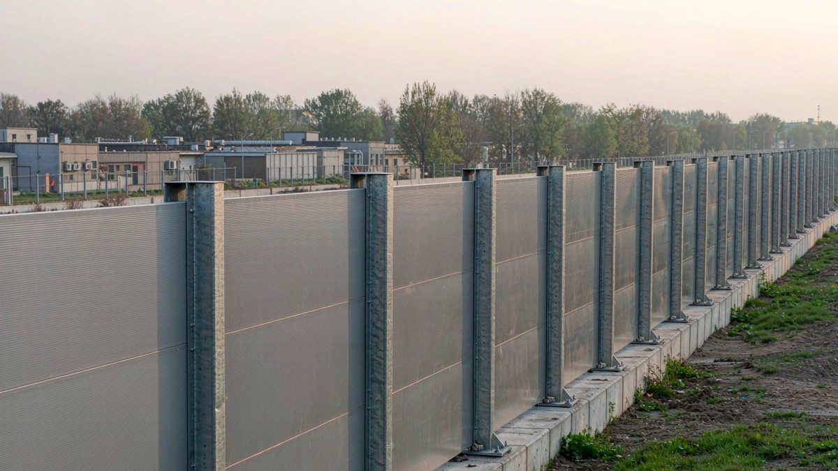
- Insert panels, bottom up. Slide into the H-section post channel, seat on the gasket, check the expansion clearance at each end.
- Top cap and closures. Cap, end closures, and corner trims last.
- Torque and mark. Torque to specification and mark each bolt with a paint stroke, so the inspector can see at a glance which ones were done.
- Touch up. Every cut, drilled hole and transport scuff, with zinc-rich paint, before handover.
Panel insertion: the four details that get skipped
Expansion clearance. A 3 m polycarbonate panel moves 4–5 mm between a cold night and a hot afternoon. Leave 10–15 mm at each end and use slotted holes with a compressible washer. Clamp it solid and the sheet crazes at the bolt holes within two or three summers.
Gasket compression. EPDM gaskets work at 25–35% compression. Under-compressed, they leak at the joint; over-compressed, they take a permanent set and leak within a year.
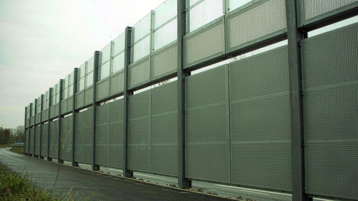
Vertical alignment of the perforated face. The perforated side goes towards the traffic. It is surprising how often a panel is installed backwards on a Friday afternoon, and it is not visible from the road side afterwards.
Top cap drainage. On a curved-top barrier, the cap must shed water to the back, not into the panel core. A cap that ponds water fills the mineral wool from the top down, and the top third of the panel is gone in two winters.
Where 3 dB disappears on site
Acoustic failures are almost never the panel. They are the joints.
- Base gap. A continuous 20 mm gap under a 3 m wall costs 2–3 dB(A). It is the single most common defect on a completed barrier, and it is invisible from 20 m away.
- Panel-to-post joint. A missing or twisted gasket creates a line leak the full height of the wall.
- End returns. The last bay is often left open to the wind, and sound goes around it. A 1 m return costs little and closes the path.
- Penetrations. Sign posts, lighting columns and camera brackets bolted through the barrier each need a sealed collar.
A simple field check: stand on the protected side at night, when traffic is light, and listen at the base of the wall. If you can hear a passing vehicle clearly through the bottom 100 mm, the seal has failed.
Productivity, so the programme is realistic
With a six-man crew and a truck crane:
- Foundation: 40–60 posts per day on competent soil with a machine auger.
- Erection: 100–150 m² of wall per day, which is 50–75 posts at 2 m spacing and 3 m height.
- Panel insertion: 60–90 panels per day, roughly 90–135 m².
- On a live carriageway with night possessions, halve all of the above.
Do not plan panel installation in wind above 10 m/s. A 3 m × 0.5 m panel is a sail, and the most common site injury on these jobs is a panel taking the crew with it.
Handover checklist
| Item | Acceptance | Record |
|---|---|---|
| Post plumb and spacing | 2 mm/m, ±5 mm | Survey sheet, every 5th post |
| Anchor torque | Per specification, typically 45–60 N·m for M12 | Torque wrench log, paint marks |
| Base seal | Continuous, no voids | Photograph before backfill |
| Panel gaskets | Continuous, 25–35% compression | Visual, 100% |
| Expansion clearances | 10–15 mm both ends | Sample check, 10% |
| Coating repair | 2 coats zinc-rich, 80 µm DFT | Photograph of each repair |
| Top line | ±10 mm over 20 m | String line photograph |
| Acoustic spot check | Insertion loss at 2 positions | Measurement report |
Five failures that show up around year five
Post corrosion at the ground line. The 300 mm above and below finished level is where water, oxygen and salt meet. It happens when the pad is not haunched, when backfill is not compacted, and when the post base is not sealed. Once it starts, the post cannot be repaired in place.
Gasket extrusion. Under-compressed gaskets creep out of the joint over a few thermal cycles and hang in strips. Cosmetic at first, then a leak.
Differential settlement at a rigid transition. Where the barrier meets a bridge abutment or a rigid wall, the flexible section settles and the joint opens. Detail a slip joint, not a fixed connection.
Base seal cracking. A rigid mortar seal on a flexible barrier cracks at every post. Use a flexible MS-polymer sealant at the post interface and mortar only in the bay.
Galvanic corrosion at stainless bolts. Stainless fasteners in a galvanised post are usually fine when dry and problematic when wet and warm. Insulating washers are cheap insurance in coastal projects.
None of these is an acoustic design problem. All of them end up as acoustic complaints.